Apologies for the many bugs in one post, let me try to mention all of them since there are quite a lot.
Bug 1: The input of an output device and the output of the output device are not the same.
I work with quite a lot of output devices and regularly find this error. Since I work in a multitude of TMD’s with input devices, an error like this completely destroys the setup.
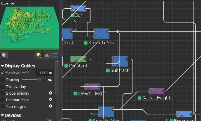
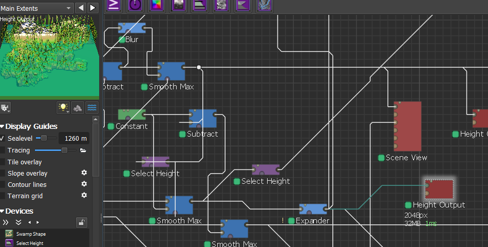
The error is displayed here;
The rightmost expander is showcased, you can see the output.
This happens randomly consistent and seems to be with combiners and outputs from what I have come across. I can not replicate it unfortunately, but it does happen regularly.
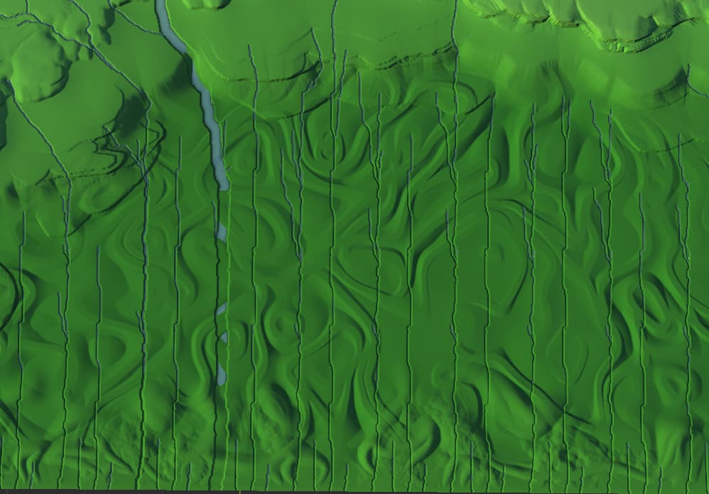
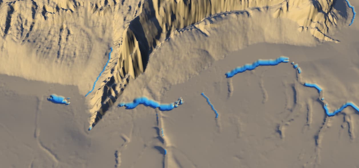
Bug 2: The Create water device streams both up hill and does not generate lakes.
For the streaming uphill I only have a screenshot in which you can vaguely see it. I did not intend to make a bug post at first hence the ‘bad’ screenshot.
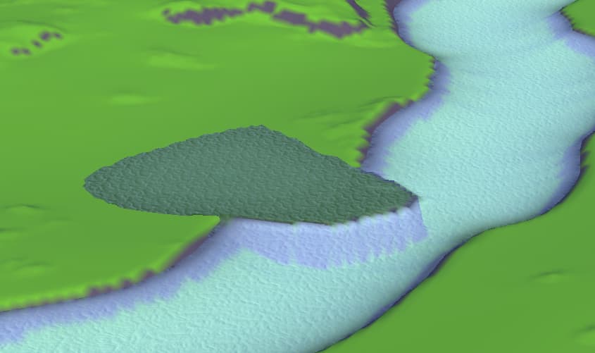
Secondly it is amazing to be able to control the lakes with the create water device. However, the depth of the lakes is not subtracted from the terrain in the same way it is done for the rivers. Creating weird looking heightmaps.
When a lake is ignored (either because the lake generation is turned off or because its below threshhold in size), WM can either carve through the drainage headwall, or make a river run uphill to get out of the lake basin. Both of these options are most useful for dealing with low quality or noisy terrain inputs - you should in general remove unwanted lake basins with the Flow Restructure device.
The toggle for the behavior is the “Carve ignored lakes” parameter. I do see an issue here, in that it is grouped under the lake settings, which disappear when unchecked. It should be moved to the river settings to make sure you can see it at all applicable times.
There are definitely some edge cases with ignored lakes that produce weird results like you’re seeing above. I hope to continue tracking them down.
Bug 3:
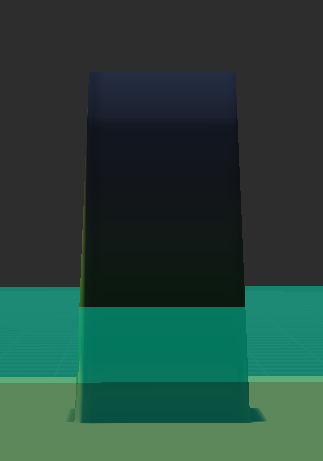
I’m fairly confident that what you’re seeing is simply the underlying heightfield slope. Since a heightfield cannot represent exactly vertical walls or overhangs, there is always a small slope even for the steepest possible map.
The above is a simpe project demonstrating zero falloff in the heightfield. There is no falloff in the above project (demonstrated by the difference values), but there is still a small slope due to the heightfield nature of the terrain. That slope should not interfere with masking in any way, since there are no intermediate values actually present in the masks, etc.
If you see something different I’d love to know about it.
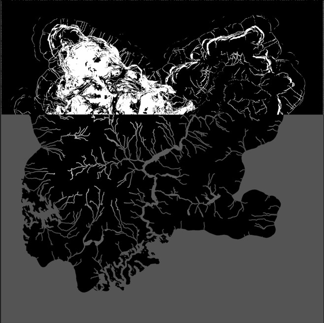
For Bug 3, I have a similar experience. For devices like Select Height, when the fallout is set to 0, I expect the grayscale image to be completely binary, but in fact, it is not. There are still some pixels between 0 and 1 at the edge of the shape.
I can reproduce this issue in the 3xxx version, but I haven’t tested it yet for 4xxx.
Unfornately I dislike the updated flow resture device due to the limitation, it will only fill basins which destroys a lot of shape (think about a volcano), so I am still using the old one.
Thank you! Looking forward to seeing the updates on this
Bug 3:
With the method you used in the TMD, you are completely right. However I think most people see the falloff=0 as a complete mask input, with binary values, 0 or 1.
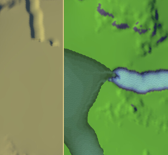
I have connected both a select slope and select height to the layout. in old version, both would show the same output (if we ignore the ground, height = 0)
However now there is quite a difference between the two outputs.
@Tomatiy@HYLK@A_Lingll in prior versions of WM, there was a small minimum falloff instead of allowing a binary mask. The HR device versions changes this to now allow a completely sharp edge.
Shape falloff:
Whether a mask or a heightfield, a step function from 0->1 in the actual data will still cover some texture distance and thus be interpolated within the display system. This is not a bug and is usually strongly desirable - but it might be unexpected if you are thinking in terms of pixels and hard edged cells,. instead of sampling.
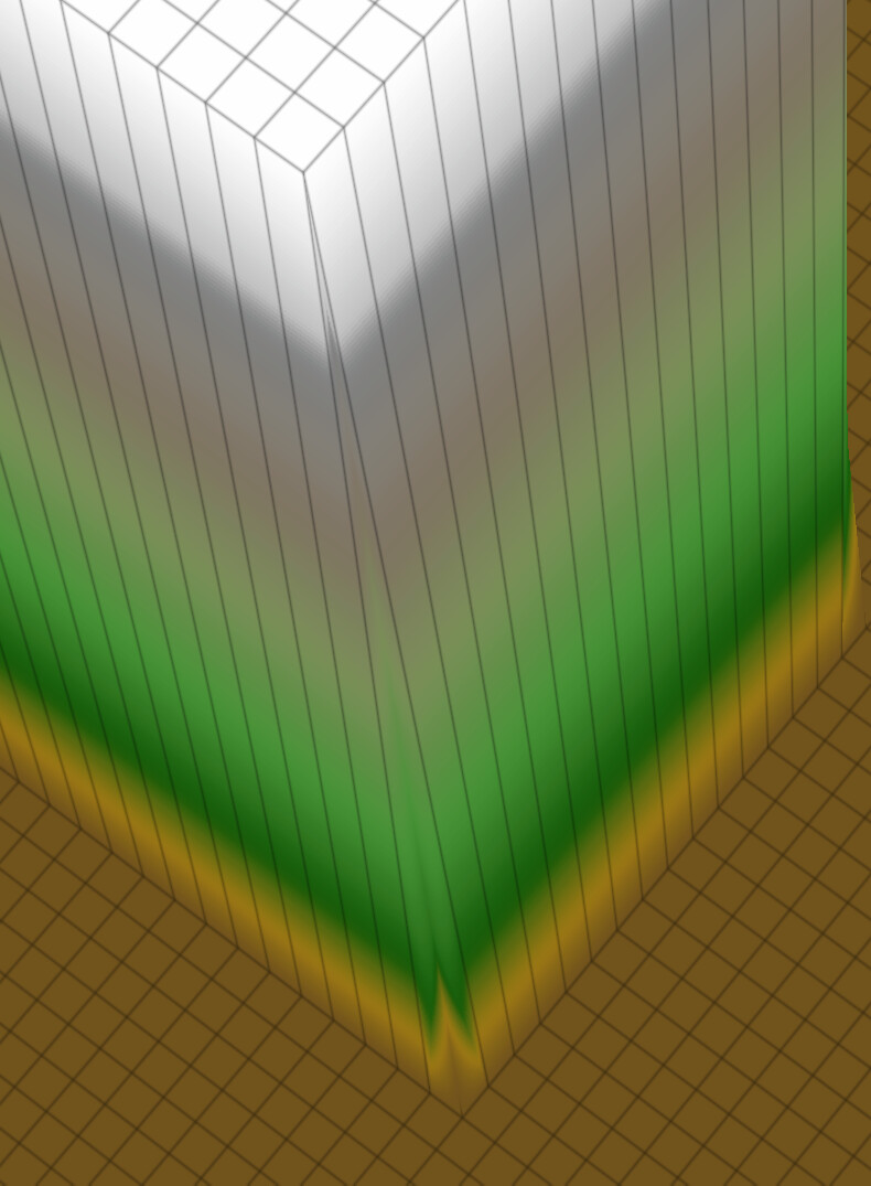
As an example, this is a layout shape with falloff=0:
Turning on the terrain grid helps understand what’s happening here (one of the reasons this display aid was added!) . Data cells are the grid crossings. You can see that the shape steps directly from 0 to 1 - there is no data (crossings of gridlines) at an intermediate value. However, the color and height is interpolated, so there is still a linear transition between them.
You can view the result in the 2D view for a non-interpolated look. If you further open the result in photoshop or another image viewer app, you should see the binary step. If you have an example case that shows something different I’d be very interested in it!
Edit:
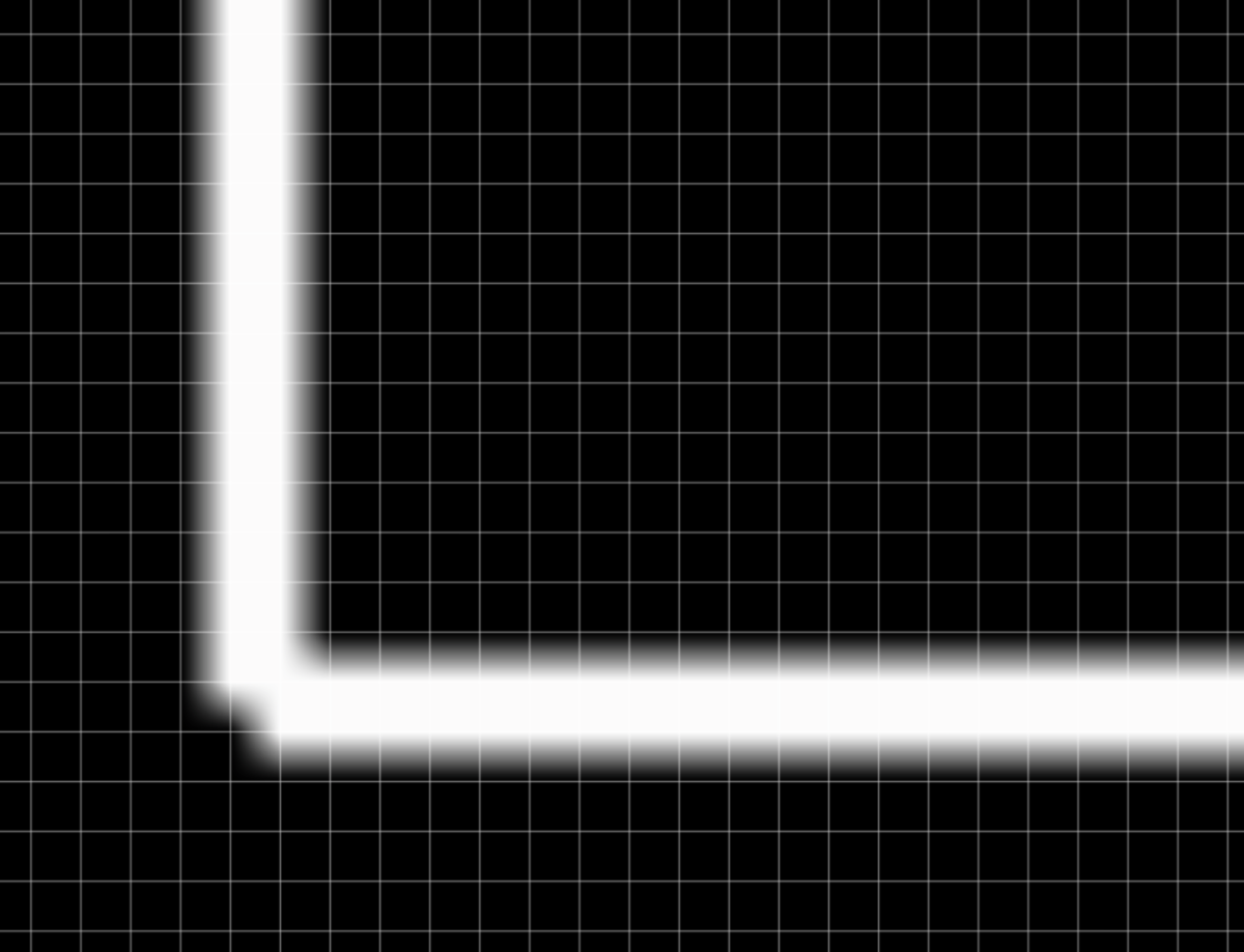
One last note. It’s worth mentioning that when using a Slope Selector on a hard edge, you’ll always get 2 pixels of width. This could be surprising, and may be part of what you’re seeing?
This is a mathematical effect of calculating slopes on a grid - calculating a slope from a grid of heights requires comparing a cell to its neighbors, which will make both the cell at the bottom of the step, and the cell at the top, have a nonzero slope.
Just like in the heightfield example above, the above is actually a hard-edged mask. It is interpolated for display…
I haven’t tested it in 4xxx but in earlier version when I needed to verify falloffs I looked at the 2D map at native/target resolution. So zooming in on pixels should show you exactly what is going on, without any interpolation…